Mini Alarms
Description:
This is a selection of small self-contained alarm circuits. They have a very
low standby current; and are suitable for battery operation.
Notes:
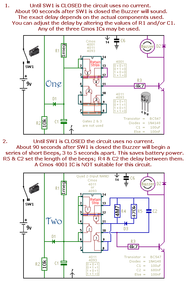
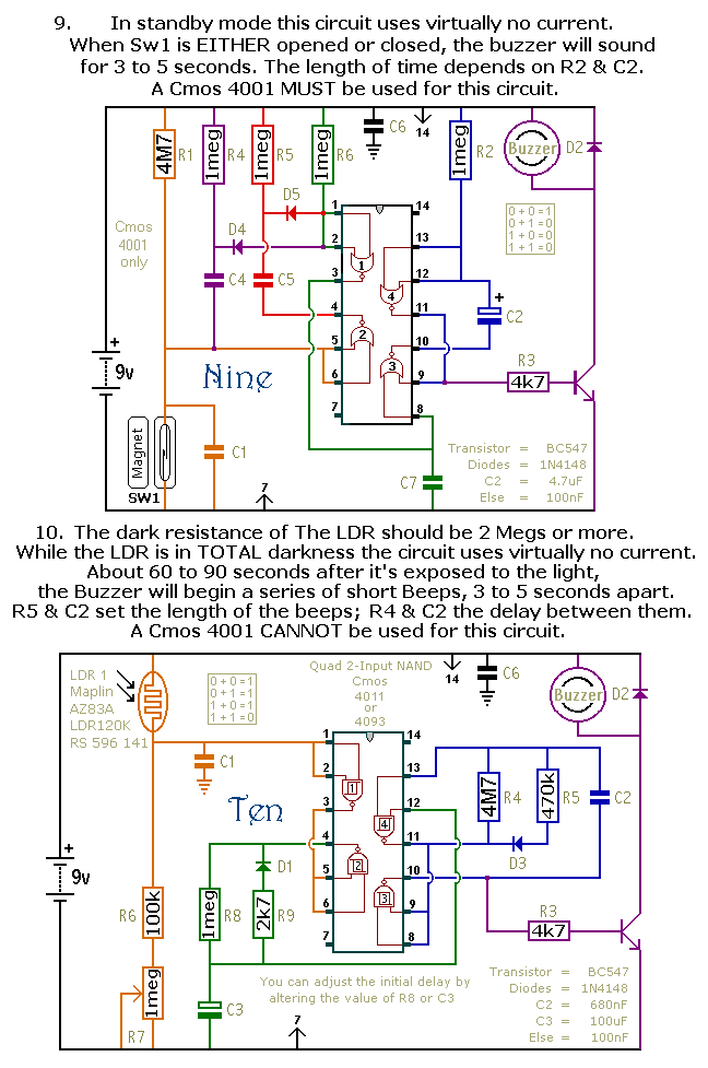
Sw1 is drawn as either a micro-switch or a magnetic-reed contact; but so long
as it does the job you can use whatever type of switch you like. Use more than
one switch if it suits your application. The output device is a "piezo" buzzer, requiring a current of about 10mA.
Provided the buzzer's voltage is suitable, the circuits will work from 5 to
15-volts. The main features of each alarm are described on the circuit diagram
itself. Each pair of circuits will print out on an A4 sheet.
The Cmos 4093 is the Schmidt-trigger version of the Cmos 4011. For present purposes the two are
interchangeable. However, the 4093 has an improved switching performance that
is most noticeable if the time periods are substantially extended.
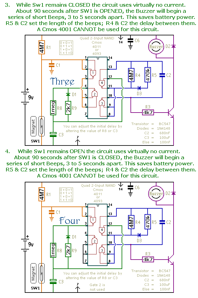
The precise length of any time period will depend on the characteristics of the
actual components used; especially the tolerance of the capacitors and the
exact switching points of the Cmos Gates.
In the case of circuits 11 & 12, treat the values of R6 & R7 as a rough
guide. The switching point of Gate 3 and the characteristics of the thermistor will determine the actual temperature range
available. Changing the value of R6 will allow you to access different areas of
the temperature scale; while changing the value of R7 will allow you to alter
the width of adjustment available.
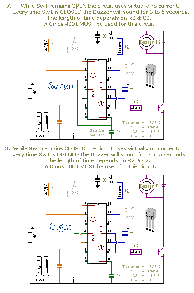
Although they are described as alarm circuits, they will have other
applications. The buzzer may be replaced by a small relay
or an optical isolator; and the timing components may be changed to produce the
required output performance. Any relay should have a coil resistance of at
least 270 ohms; but for battery operation, the higher the better. If you're
using an optical isolator, connect a 1k resistor in series with its LED.

Return to Alarm Circuits