STROBE ALARM
Schematic:
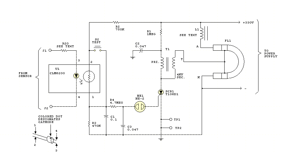
Notes:
This strobe gives a visual
indication of a sensor input. The input signal causes U1, a light dependent
resistor, to charge C1 and C3 through R4. When NE1 fires, C3
discharges into SCR1, which triggers it and causes C2 to discharge through
trigger transformer T1, which triggers Flashlamp FL1.
The 330-V supply should have about 50 to 100 uF
output capacitance. L1 supplies about 25-mH inductance to prolong the flash and
the life of FL1.
Return to Display Circuits