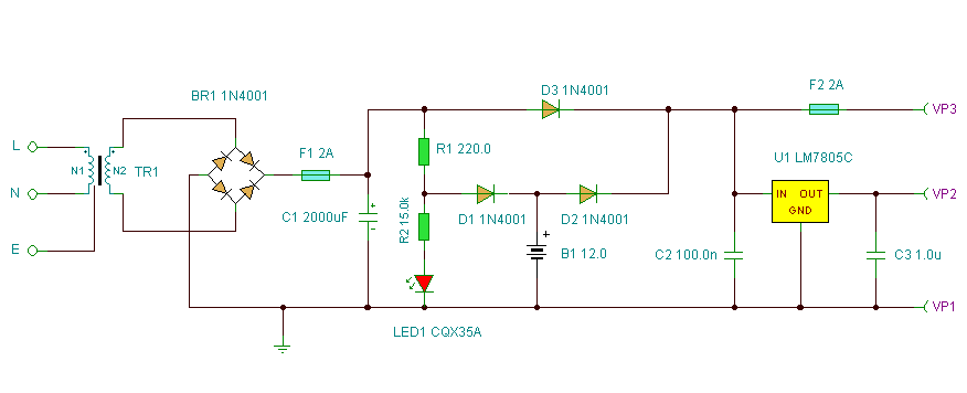
Basic UPS Power Supply
Description
This circuit is a simple form of the commercial UPS,
the circuit provides a constant regulated 5 Volt output and an unregulated 12
Volt supply. In the event of electrical supply line failure the battery takes
over, with no spikes on the regulated supply.
Notes:
This circuit can be adapted for other regulated and unregulated voltages by
using different regulators and batteries. For a 15 Volt regulated supply use
two 12 Volt batteries in series and a 7815 regulator. There is a lot of
flexibility in this circuit.
TR1 has a primary matched to the local electrical supply which is 240 Volts in
the
Between terminals VP1 and VP3 the nominal unregulated supply is available and a
5 Volt regulated supply between VP1 and VP2. Resistor R1 and D1 are the
charging path for battery B1. D1 and D3 prevent LED1 being illuminated under
power fail conditions. The battery is designed to be trickle charged, charging
current defined as :-
(VP5 - 0.6 )
/ R1
where VP5 is the unregulated DC power supply voltage.
D2 must be included in the circuit, without D2 the battery would charge from
the full supply voltage without current limit, which would cause damage and
overheating of some rechargeable batteries. An electrical power outage is
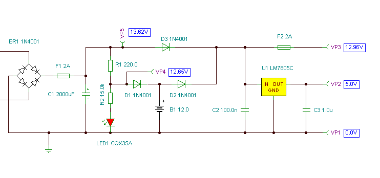
simulated below:
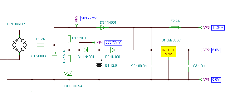
Note that in all cases the 5 Volt regulated supply is maintained constantly,
whilst the unregulated supply will vary a few volts.
Standby Capacity
The ability to maintain the regulated supply with no electrical supply depends
on the load taken from the UPS and also the Ampere hour capacity of the
battery. If you were using a 7A/h 12 Volt battery and load from the 5 Volt regulator was 0.5 Amp (and no load from the unregulated
supply) then the regulated supply would be maintained for around 14 hours.
Greater A/h capacity batteries would provide a longer standby time, and vice
versa.
Return to Power Supply Circuits