A BIPOLAR REGENERATIVE RECEIVER
Contrary to what some radio experimenters think, a bipolar regenerative design
can be made to work efficiently. The major concern is the low input impedance
of the detector-amplifier bipolar stage. Nevertheless, it can be easily
compensated with positive feedback or regeneration. A sufficient amount of
regeneration can make tuning astonishingly sharp. Another concern is the
quality of the detected audio. This, to my knowledge, is subjective. The
quality of sound coming out from an earphone can be rated good or fair by two
different people. I would suggest that you decide by yourself. So, come on and
try the following schematic for the 530 kHz to 1650 kHz AM Broadcasting Band.
Please notice that the 475 pF variable capacitor
tunes in the stations whereas the 200 pF variable
capacitor controls regeneration. The latter is known as the throttle capacitor.
L2 is the tickler coil. In order to regeneration to take place, L1 and L2 must
be correctly phased ( very important! ).
The power consumption is very low. The 2N3904 drains some 60 uA from the 9 volt battery and the AC126, about 0.5 mA.As a benchmark, medium powered ( 5 to 10 kw ) local stations within 25 km from my site are heard as
fair to loud audio signals.
The audio output stage has no external bias, and doesn't need any. This is
because Iceo, the leakage collector current ( about 0.5 mA in my prototype ),
is sufficient to build up a usable Beta ( or current amplifying factor ) in the
germanium AC126 transistor. This is a bit unusual but it works fine. Also, the
signal detection is carried out by the 2N3904 transistor, as it is driven,
thanks to regeneration, into its non-linear region. In other words, it works as
an amplifier-detector.
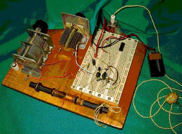
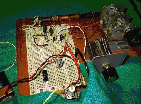
Photographs of Ramon's Prototype
Return to RF Circuits