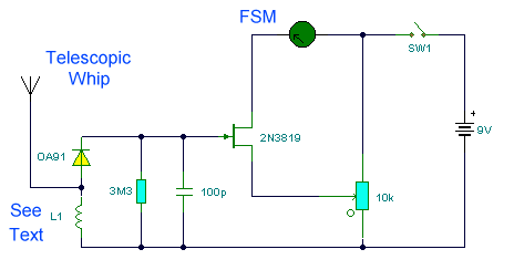
Field Strength Meter
Descripton
This is a wide band signal strength
meter circuit which responds to small changes in RF energy, designed to be used
for the VHF spectrum and will respond to AM or FM modulation or just a plain
carrier wave.
Notes:
This circuit measures radio field strength by converting the signal to DC and
amplifying it. This field strength meter was designed for VHF frequencies in the range 80 -110 MHz.The inductor L1 is 4 to 6 turns of 20swg
wire air spaced wound on a quarter inch former or similar. Alternatively
an inductor of value 0.15 - 0.35uH will suffice. Sensitivity is not as good as
I would have liked, but a small 9 volt battery transmitter will deflect the
meters needle from a distance of up to two feet from the FSM. Higher power
transmitters give higher signal strength readings and of course from much
further away.The meter used was a signal meter with FSD of 250uA.
The FET used in this circuit is a general purpose 2N3819. A small telescopic
whip antenna is used for signal pickup. The 10k preset resistor is used to
adjust bias of the FET circuit; with no transmitter present the meter reading
is zero, adjust preset if not. The RF signal, whether modulated or just a plain
carrier, is rectified and converted to DC by the diode,capacitor
and 3.3M resistor. This small DC voltage just enough to upset
the bias of the circuit and hence cause a deflection of the meter.
Return to RF Circuits