| Read the page
on potential dividers.
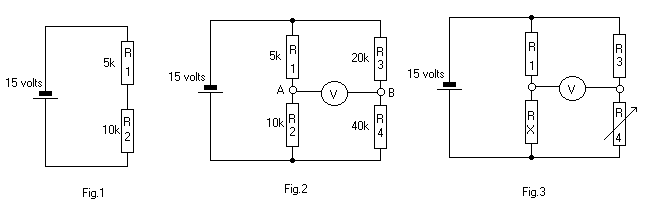
In Fig.1, the
15 volts will be divided across the two resistors, according their proportion
of the total resistance, 15k.
In Fig.2 we have
the same potential divider plus R3 and R4 across the battery.
|
| Using the same
calculations as for R1 and R2, we find that the voltage across R3 = 5 volts
and across R4 = 10 volts.
The voltage has been divided in the same proportions. This is because the ratio R1/R2 is the same as the ratio R3/R4, that is, 1:2. The meter, connected
between points A and B will indicate zero.
If the two ratios
are not the same, then the voltages at the two terminals of the meter will
be different.
In Fig.3, Rx
is of unknown value and the probability is that the bridge is unbalanced,
indicated by a reading on the meter.
R4 can be fitted with a pointer and a calibrated scale to give a direct reading of Rx without the need for calculations. This is the basis of more complex bridge circuits. |

Copyright Graham Knott 1999