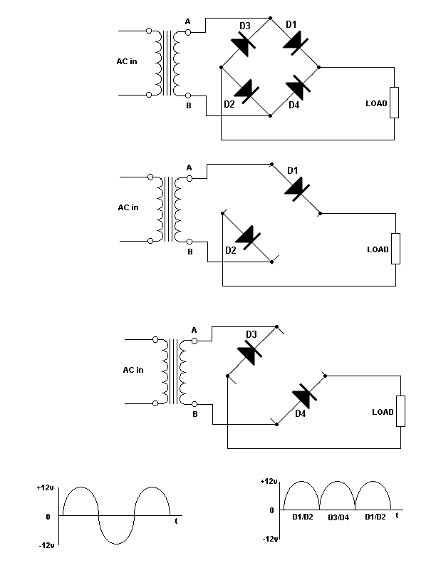
| The left hand
waveform shows the input voltage (50 Hz AC in the UK).
The voltages
at points A and B on the transformer are changing in opposite directions.
When A is increasing
in a positive direction, B is increasing negatively.
It is like the
opposite ends of a see-saw.
During the first
half cycle, A is positive and B is negative.
D1 has positive
on its anode, D2 has negative on its cathode.
Both are forward
biased.
Current flows
around the circuit formed by these diodes, the load and the transformer
winding, as shown in the second diagram.
The current
flowing up through the load produces a pulse of voltage across the load
as shown in the right hand waveform.
During the next
half cycle, A is negative and B is positive.
D4 has positive
on its anode, D3 has negative on its cathode.
Both are forward
biased.
Current flows
around the circuit as shown in the bottom diagram, again flowing in the
same direction through the load and producing another pulse of voltage.
Since the full
cycle is used this circuit is called a FULL-WAVE rectifier.
Since there are
two pulses for each cycle of input, there are 100 pulses per second out
(in the UK).
The pulsating
DC can be smoothed with a reservoir capacitor, as in the half-wave rectifier
circuit.
Since the pulse
frequency is higher than that of the half-wave rectifier, it is easier
to smooth. |


