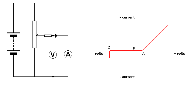
| The circuit
enables the forward bias voltage across the diode to be set anywhere from
zero to the maximum positive voltage of the battery.
The voltage and
corresponding current is recorded on the meters.
If these values
are plotted we obtain the curve shown in the top right quarter of the graph.
Note that as
the voltage increases the current stays at zero, until the voltage reaches
a certain value.
The current
then begins to increase quite rapidly.
It is at this
point that the barrier potential has been overcome and the diode begins
to conduct.
This value is
about 0.6 volts for silicon diodes and 0.3 volts for germanium types.
If the battery
is reversed and a graph again plotted for current against voltage, we obtain
the curve in the bottom left quarter of the graph.
It can be seen
that as the voltage is increased in the reverse direction, there is no
current flowing until a certain value of voltage is reached and the current
suddenly increases to a high value.
This is the
breakdown or Zener point and is used in Zener diodes.
|


