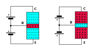
| The emitter/base
junction is forward biased.
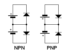
The collector/base junction is reversed biased. There is an explanation of biasing on one of the diode junction pages. The middle diagram
shows the two junctions as two diodes.
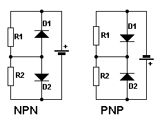
The bottom diagram shows the junctions being correctly biased using just one battery. Note that there
is 0.6 volts across the base/emitter junction when it is forward biased,
for a silicon transistor. (0.3 volts for a germanium one).
|
