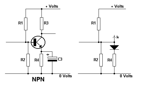
| R1 and R2 bias
the transistor in class A so that a steady dc collector flows.
R4 is the emitter
stabilising resistor.
When collector
current flows it causes the transistor to heat up.
This causes
the base current to increase which in turn causes the collector current
to rise.
This rise in
collector current causes the temperature to increase even more, and the
base and collector currents continue increasing.
This behaviour
is called THERMAL RUNAWAY and will destroy the transistor.
If we consider
the emitter/base junction as a diode as shown in the right hand diagram
we can see that the base (anode) voltage is fixed by R1 and R2.
If the collector
current tries to rise due to heating, then the voltage across R4 will try
to rise, making the emitter (cathode) more positive.
This would reduce
the voltage across the junction (diode) making it less forward biased and
reducing the base current and hence the collector current, which was trying
to rise.
Therefore the
circuit has been stabilised against thermal runaway.
However, if an
ac signal is applied to the base, the varying collector current will cause
a varying voltage across the emitter resistor.
This voltage
will follow the base voltage.This means that the base/emitter (anode/cathode)
voltage will be constant instead of the base varying with respect to the
emitter.
To fix this,
the emitter is joined to earth, as far as the ac signal is concerned, by
the emitter decoupling capacitor. |


