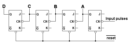

| Note that the
J and K inputs are taken high so that the flip-flops toggle on the clock
pulses.
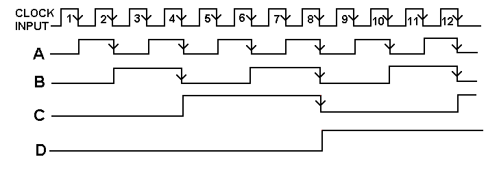
The Q output of each flip-flop changes state on the negative going edge of the clock input pulse. Looking at the diagram below the count starts with ABCD all low, giving a count of 0000. After clock pulse 1, the least significant bit, A is high, 0001. After pulse 2, A is low and B is high, 0010, equivalent to decimal 2. After 12 pulses, A and B are low and C and D are high, 1100, equivalent to decimal 12. On clock pulse 16 the counter resets to 0000. The count can be set to 0000 by pulsing the Reset line low. The flip-flops cannot change state until the preceding one has done so. This means gives rise to a delay in the the system due to the propagation delay of each stage. This causes a
RIPPLE THROUGH effect.
|

